
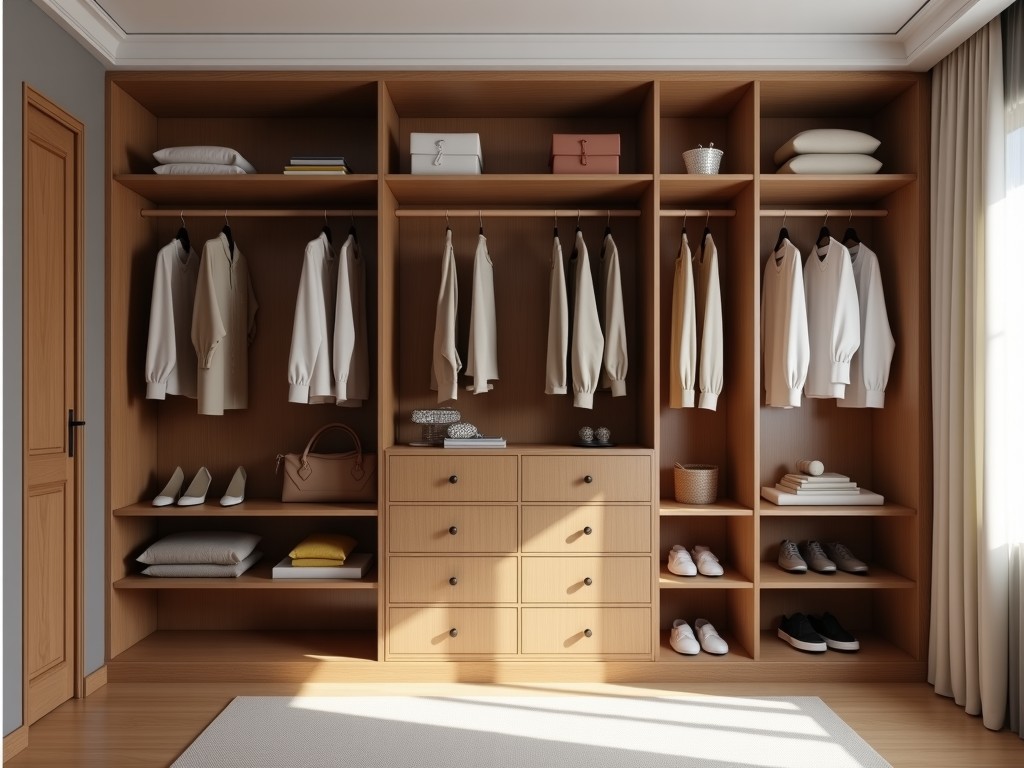
Each project begins with a detailed review of the client’s spatial constraints, load requirements, and finish specifications. Engineers translate these inputs into a parametric model that defines
Inquire NowEach project begins with a detailed review of the client’s spatial constraints, load requirements, and finish specifications. Engineers translate these inputs into a parametric model that defines panel thickness, hardware placement, and adjustment ranges.
The model outputs a bill of materials that lists exact dimensions for each component, allowing the production team to generate CNC programs without manual rework. This approach reduces tolerance stack‑up and ensures repeatable fit across multiple units.
Clients receive a digital proof that includes exploded views, assembly sequences, and estimated weight per module. Approval of the proof triggers the release of tooling files to the shop floor.
Material grades are selected after evaluating the client’s expected load cycles, ambient humidity, and cleaning regimen. Test coupons are produced and subjected to flexural and impact tests before full‑scale production.
The facility operates five‑axis CNC routers with positioning accuracy ± 0.05 mm and repeatability ± 0.02 mm. Panel edges are finished with either a 0.5 mm radius bullnose or a 90° square edge, depending on the design intent.
Hardware insertion uses programmable torque drivers calibrated to 0.1 Nm increments, ensuring consistent cam lock or connector preload. All drilled holes undergo a secondary deburring pass to remove burrs larger than 0.1 mm.
Production runs are tracked via a Manufacturing Execution System (MES) that logs cycle time, tool wear, and inspection results for each batch. This data enables predictive maintenance and minimizes scrap.
Inspection occurs at three stages: incoming material verification, in‑process dimensional checks, and final assembly audit. Incoming boards are tested for moisture content (target ≤ 8 %) and formaldehyde emission (E1 class ≤ 0.1 ppm).
During machining, a laser probe measures critical features such as hole diameter and shelf pocket depth; deviations beyond ± 0.1 mm trigger an automatic halt and operator review.
Finished units undergo a load test where each shelf is subjected to 125 % of its rated capacity for 10 minutes; deflection is measured with a dial indicator and must remain below 2 mm. Units that pass receive a QR‑coded traceability tag linking to the batch record.
Custom closets are frequently integrated into clean‑room gowning areas where modular storage must accommodate ISO‑class airflow requirements. The smooth, non‑porous surfaces minimize particle retention and allow for easy disinfection.
In automotive assembly plants, closets house tooling and personal protective equipment. The aluminum‑framed versions provide magnetic compatibility for tool holders and resist oil‑based contaminants.
Warehouse distribution centers use the high‑load shelving configurations to store bulk‑packed components; the adjustable shelf pins enable reconfiguration as SKU profiles change without dismantling the unit.
| Parameter | Typical Value / Range | Notes |
|---|---|---|
| Panel Thickness | 16 mm – 25 mm | Selected per load case | Shelf Load Capacity | Up to 200 kg (uniformly distributed) | Deflection ≤ L/200 |
| Edge Finish | Bullnose 0.5 mm or Square 90° | Customer‑specified |
| Hardware Type | Cam lock, dowel, or concealed connector | Torque calibrated per material |
| Surface Finish | Melamine, PVC laminate, or veneer | Abrasion resistance ≥ 300 cycles |
| Maximum Unit Height | 3000 mm (single module) | Taller assemblies use intermediate supports |
Yes. The parametric model accepts arbitrary width, depth, and height inputs. Adjustments are limited only by material sheet size and structural stability; for spans exceeding 1200 mm, intermediate stiffeners are recommended.
A preliminary layout sketch, anticipated load per shelf, environmental conditions (temperature, humidity, chemical exposure), and preferred finish. Providing a CAD file speeds up the quoting process.
Moisture‑resistant MDF with a phenolic coating, or aluminum extrusions with anodized finish (minimum 15 µm). Both options pass ASTM B117 salt‑spray testing for 500 hours with < 5 % weight loss.
Statistical process control (SPC) charts monitor critical dimensions. Each lot receives a first‑article inspection and a random sample of 5 % is subjected to the full load and deflection test.
Units are wrapped in polyethylene film, placed on corrugated pallets with corner protectors, and strapped with PET bands. For overseas shipments, a heat‑sealed barrier bag with desiccant is added to control moisture.
Lead time ranges from 3 to 6 weeks after approval of the digital proof, depending on material availability and order complexity. Expedited options are available for critical projects.
Share your project specifications, including dimensions, load expectations, and environmental factors. Our engineering team will review the details and provide a detailed feasibility report with lead‑time and cost estimates.
Request a Technical ConsultationQueenswood delivers modern bathroom solutions through original design, advanced manufacturing, and reliable quality for customers worldwide.


Middle of Xingang East Road, Haizhu District, Guangzhou City, Guangdong Province

